In 2019, a galvanizing plant in Vietnam called us about their new pickling line scrubber. The local contractor had built it — φ1.8m, 2.5m tall, 1,200 kg of ceramic packing inside. On paper, the design checked out. In operation, the pressure drop ran triple the predicted value. The column flooded twice in the first month. When we opened the inspection port, the answer was staring at us: the packing was bone-dry in four places, the liquid distributor was the wrong type for that diameter, and the L/G ratio — which nobody had calculated — was 0.3 when the packing needed 1.0 minimum. The fix cost $14,000 and three weeks of downtime. The original calculation had skipped three checks that would have caught every problem before a single sheet of PP was welded.
Most gas scrubber design calculation guides give you formulas. Formulas are cheap. What’s expensive is not knowing which checks to run after the formulas, in what order, and what to do when the numbers don’t close.
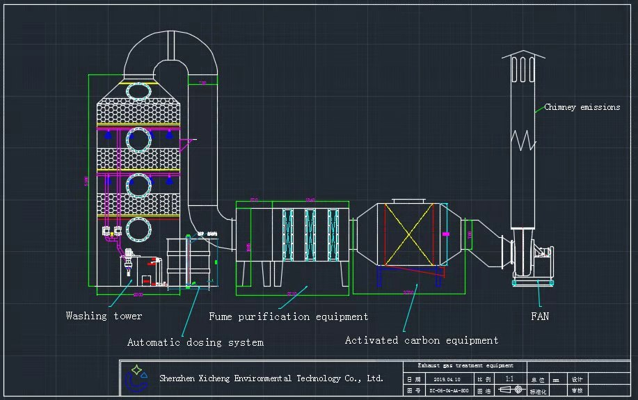
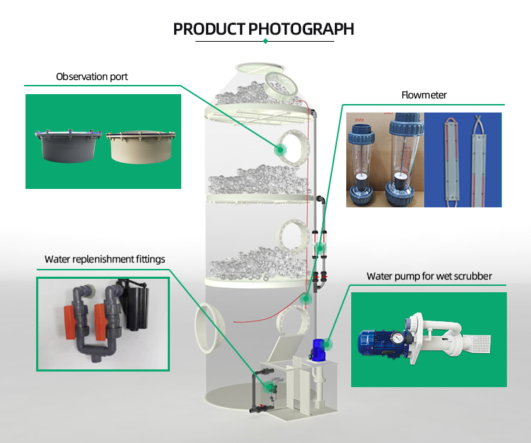
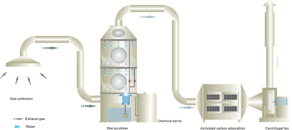
For specifications and pricing on wet scrubber systems sized to your exact gas stream, browse our wet scrubber product catalog.
Key Takeaways
- A gas scrubber design calculation starts with five verified inputs — gas flow rate, contaminant type and inlet concentration, target removal efficiency, gas temperature, and available footprint. None of these can be guessed from a project spec sheet alone.
- Column diameter comes from the Souders-Brown equation with K = 0.06 m/s for packed beds (0.10–0.15 m/s for spray towers), always derated to 70–80% of flooding velocity. For 10,000 m³/h with 2-inch Pall rings, the converged diameter is 1.4 meters.
- Packed bed height uses the HTU-NTU method: NTU = 3.0 for 95% removal, HTU ≈ 0.5 m for 2-inch PP Pall rings with reactive absorption, giving 1.5 m of packed depth. Below 0.6 m packed depth, skip the packing and use a spray tower.
- The minimum wetting rate check is the step most designs skip — and the one that triggers iteration. Our HCl example at 10,000 m³/h needed three rounds of diameter and L/G adjustment before the liquid flux met MWR. Run this check or ship a dry column.
- Material selection hinges on temperature and gas chemistry: PP handles most acid gases below 80°C at the lowest cost. FRP with vinyl ester resin covers 120–180°C and caustic service. Stainless steel and Hastelloy are reserved for chemistries where plastics fail — and they multiply equipment cost by 2–12×.
Where Design Calculations Actually Start
What You Need Before Touching a Formula
Most engineers jump straight to diameter and height. That’s backwards. A gas scrubber design calculation begins with five numbers — and if any one of them is wrong, nothing downstream holds.
The five inputs every scrubber design hangs on:
- Gas flow rate (Q_g) — the volume of contaminated air moving through the system, measured in m³/h or ACFM. For a typical pickling line exhaust, this runs 5,000 to 15,000 m³/h. For a chemical reactor vent, you might see 500 to 3,000 m³/h. Get this from actual measurements, not nameplate ratings. We’ve seen fans degrade by 15–20% over 3 years and the design flow no longer matches reality.
- Contaminant type and inlet concentration (C_in) — what are you removing and how much of it is there? HCl from steel pickling typically runs 50–200 mg/m³. SO₂ from boiler exhaust might sit at 500–2,000 ppm. H₂S from wastewater treatment varies wildly — 10 to 10,000 ppm depending on the process. Concentration determines everything downstream: scrubbing solution chemistry, packing depth, and material selection.
- Target removal efficiency (η) — how clean does the outlet need to be? Regulatory limits set this number. For HCl in most jurisdictions, you need ≥95% removal to stay under the 10 mg/m³ emission threshold. For SO₂, the target is often 98–99%. Write this number down as a decimal — 0.95, not 95% — because every formula uses it that way.
- Gas temperature — inlet temperature determines whether you need a quench section before the packed bed. PP scrubbers soften above 80°C. FRP handles up to 180°C continuously. If your inlet gas is above 120°C, you’re looking at a quench spray or a stainless steel first stage before the main packed section.
- Available footprint and height clearance — a φ1.4m × H4.6m scrubber won’t fit in a 3-meter ceiling space. Crossflow designs save height but need more floor area. Counterflow vertical towers are compact in footprint but tall — typical height-to-diameter ratios run 3:1 to 7:1. Measure the space before you calculate the tower.
The 5 Numbers That Drive Every Scrubber Design
Here’s the quick-reference table we use internally. Match your scenario to the closest row, and you’ll know whether your design is in normal territory or needs special handling:
| Parameter | Typical Range | If Outside Range |
|---|---|---|
| Gas flow rate | 1,000–50,000 m³/h | Below 1,000: consider a packaged unit. Above 50,000: split into parallel trains |
| Inlet concentration (acid gases) | 10–500 mg/m³ | Above 500: two-stage scrubbing or higher L/G ratio |
| Target efficiency | 90–99% | Above 99%: add a second packed bed or chemical additive |
| Inlet temperature | 20–80°C (PP); 20–180°C (FRP) | Above 180°C: add quench section or use SS316/stainless first stage |
| Available height | 3–8 m typical | Below 3 m: crossflow design. Above 8 m: standard counterflow works |
Once these five numbers are pinned down — and you’ve verified them against actual site conditions, not just the project spec sheet — you’re ready for the formulas. Skip this step and you’ll design a scrubber that works on paper and fails in the field.
Column Diameter: The First Number That Matters
Diameter sets the gas velocity inside the tower. Get the diameter wrong and you get one of two outcomes: droplets carried out the stack (too small) or gas bypassing the scrubbing zone entirely (too large). Neither one is fixable after the scrubber is built.
The Velocity Constraint
Inside a packed bed scrubber, gas moves upward against liquid spraying downward. Too fast — above 2.0–2.5 m/s superficial velocity — and the gas holds the liquid up. Flooding starts at the bottom, climbs the column, and pressure drop spikes. Too slow — below 0.3 m/s — and the liquid channels through the packing instead of wetting it evenly. Either way, removal efficiency drops.
For hollow spray towers with no packing, the sweet spot in scrubber design calculation is 1.0–1.5 m/s. For packed beds using random packings like Pall rings or Raschig rings, operate at 0.3–0.5 m/s. These numbers come from decades of operating data — not from a textbook equation. Every manufacturer we’ve worked with converges on the same ranges.
Target 70–80% of the flooding velocity. The flooding velocity itself comes from the Eckert generalized correlation — a log-log plot of capacity factor versus flow parameter. Most engineers don’t solve this by hand anymore. But you need to know whether your result is in the right ballpark.
Souders-Brown: The Working Engineer’s Shortcut
The Souders-Brown equation gives a quick, defensible diameter estimate without running the full Eckert correlation:
u_sg = K × √((ρ_l − ρ_g) / ρ_g)
Where:
- u_sg = superficial gas velocity (m/s)
- K = Souders-Brown coefficient — use 0.05–0.10 m/s for packed scrubbers, 0.10–0.15 m/s for spray towers without packing
- ρ_l = liquid density — for water-based scrubbing solutions, ~1,000 kg/m³
- ρ_g = gas density — air at 25°C is ~1.2 kg/m³; hotter gases are less dense and increase velocity
Plug in the numbers. At 25°C with a water scrubber: u_sg = 0.08 × √((1000 − 1.2) / 1.2) ≈ 2.3 m/s — but that’s the value before the 70% derating. Apply the safety factor and you’re at ~1.6 m/s design velocity. For packed beds, use K = 0.06, which lands at ~1.7 m/s before derating.
Then diameter follows directly:
D = √(4 × Q_g / (π × u_sg × 3600))
For Q_g = 10,000 m³/h at u_sg = 1.6 m/s: D = √(4 × 10000 / (3.14 × 1.6 × 3600)) = 1.49 m. Round up to the nearest standard size — 1.5 m diameter.
Quick Reference: Diameter vs Airflow
Here’s a pre-calculated scrubber sizing table based on a packed bed scrubber operating at 0.5 m/s superficial velocity with water scrubbing at 25°C:
| Airflow (m³/h) | Calculated Diameter (m) | Standard Size (m) | Actual Velocity (m/s) |
|---|---|---|---|
| 1,000 | 0.84 | 0.9 | 0.44 |
| 3,000 | 1.46 | 1.5 | 0.47 |
| 5,000 | 1.88 | 2.0 | 0.44 |
| 10,000 | 2.66 | 2.8 | 0.45 |
| 15,000 | 3.26 | 3.4 | 0.46 |
| 20,000 | 3.76 | 3.8 | 0.49 |
| 30,000 | 4.61 | 4.6 | 0.50 |
| 50,000 | 5.95 | 6.0 | 0.49 |
A note on rounding: always round up to the next standard diameter. Rounding down pushes velocity higher, and you’ve already applied your safety factor. Don’t eat into it twice.
Packed Bed Height: Where Mass Transfer Happens
Diameter controls velocity. Height controls how long the gas and liquid touch each other. That contact time — residence time in the packed zone — is what determines whether you hit 95% removal or 80%.
HTU-NTU: Height of a Transfer Unit × Number of Transfer Units
The standard packed bed height calculation in any gas scrubber design uses the HTU-NTU method. Think of it as two separate questions: how hard is the separation (NTU), and how efficient is your packing at doing that separation per meter of depth (HTU).
Step 1 — Calculate NTU (Number of Transfer Units):
For dilute gas systems where the equilibrium line is roughly straight, use:
NTU = ln(y_in / y_out)
Where y_in and y_out are inlet and outlet pollutant mole fractions. For 95% removal: NTU = ln(1 / 0.05) = ln(20) = 3.0. For 99% removal: NTU = ln(1 / 0.01) = 4.6. Every extra 9 of removal costs you about 1.6 additional transfer units — and about 50% more packing height.
For systems where the absorption factor AF = L/(m × G) is not close to 1, the full formula applies:
NTU = ln[ (y_in / y_out) × (1 − 1/AF) + 1/AF ] / (1 − 1/AF)
When AF > 1 (liquid-rich operation), NTU decreases — the scrubbing solution has excess capacity and each meter of packing does more work. When AF < 1 (gas-rich), the column runs lean on liquid and NTU increases substantially.
Step 2 — HTU (Height of a Transfer Unit):
HTU depends on packing type, gas velocity, and liquid distribution. For random packings in industrial scrubbers, typical HTU values:
- 1-inch Pall rings: 0.3–0.5 m
- 2-inch Pall rings: 0.5–0.8 m
- 3.5-inch Pall rings: 0.7–1.0 m
- Structured packing (Mellapak 250Y): 0.2–0.4 m
Smaller packing gives lower HTU — better mass transfer per meter. But it also increases pressure drop and clogs more easily. In a dirty gas stream with particulates, 2-inch rings are the practical minimum.
Step 3 — Packed height:
H_pack = NTU × HTU
For our HCl scrubber at 10,000 m³/h targeting 95% removal with 2-inch Pall rings: H_pack = 3.0 × 0.6 = 1.8 m. Add 0.3 m for liquid distribution at the top and 0.3 m for gas distribution at the bottom, and you’re at 2.4 m total packed section height.
Rules of Thumb for Packing Depth
Across wet scrubber installations we’ve supplied, packed bed depths fall into predictable bands:
| Application | Typical Packed Depth (m) | NTU Required |
|---|---|---|
| Easy removal — highly soluble gas, low inlet concentration (e.g., HCl in water at 50 mg/m³) | 0.6–1.2 | 1.5–2.5 |
| Standard removal — moderately soluble gas, moderate concentration (e.g., SO₂ with caustic at 500 ppm) | 1.2–1.8 | 2.5–3.5 |
| Difficult removal — low solubility gas or high inlet concentration (e.g., H₂S at 5,000 ppm) | 1.8–2.5 | 3.5–5.0 |
| Critical removal — sub-ppm outlet requirement (e.g., HF in semiconductor exhaust) | 2.5–3.5 | 5.0–7.0 |
One hard rule: never go below 0.6 m packed depth. At shallower depths, liquid distribution dominates and you get inconsistent wetting. At that point, switch to a spray tower without packing — it’s cheaper and the performance is the same.
Packing Type Matters More Than You Think
Packings are not interchangeable. The right choice shaves 30–40% off your column height. The wrong choice doubles your pressure drop and needs replacement in two years. Here’s how the main types compare for industrial gas scrubbing:
| Packing Type | Surface Area (m²/m³) | Pressure Drop (Pa/m) | Liquid Hold-up | Fouling Resistance | Best For |
|---|---|---|---|---|---|
| 1″ Pall Ring (PP) | 210 | 200–400 | Low | Good — open structure resists plugging | Dirty gas streams, particulate-laden exhaust |
| 2″ Pall Ring (PP) | 100 | 100–250 | Very Low | Excellent — largest openings | High-volume, low-concentration acid gas scrubbing |
| Raschig Ring (ceramic) | 180 | 400–800 | Medium | Poor — dead zones trap solids | High-temperature or corrosive applications where plastics fail |
| Tri-Packs® (PP) | 160 | 150–350 | Medium | Very Good — ribbed design prevents nesting | General-purpose acid scrubbing, odor control |
| Structured Packing (Mellapak 250Y) | 250 | 50–150 | Low | Poor — narrow channels clog easily | Clean gas, highest efficiency, low pressure drop priority |
| PP Hollow Ball (φ38–50mm) | 120–180 | 100–300 | High | Excellent — balls tumble and self-clean | Dust-laden streams, turbulent bed scrubbers |
For most industrial acid gas applications, 2-inch PP Pall rings are the default choice. They handle the temperature range, they resist fouling, and they’re stocked by every packing supplier. Structured packing is tempting on paper — lower pressure drop, higher efficiency — but it plugs, and a plugged structured packing column needs a crane to pull the elements. Field experience beats datasheet numbers every time.
Liquid-to-Gas Ratio: The Forgotten Parameter
L/G ratio is the parameter nobody talks about at design meetings — until the scrubber fails its performance test. It determines whether your packing actually gets wet, whether your pump is sized correctly, and whether you’re dumping money into oversized recirculation.
How Much Scrubbing Liquid Do You Need
The liquid-to-gas ratio (L/G) is the mass or volume of scrubbing liquid circulated per unit volume of gas treated. For industrial packed bed scrubbers, the working range is narrow:
| Scrubber Type | L/G Ratio (L liquid / m³ gas) | Typical Value |
|---|---|---|
| Spray tower (no packing) | 0.5–1.5 | 0.8 |
| Packed bed — easy removal | 0.5–1.0 | 0.7 |
| Packed bed — standard | 0.7–1.2 | 0.9 |
| Packed bed — difficult removal | 1.0–2.0 | 1.5 |
| Venturi scrubber | 0.5–1.5 | 1.0 |
Below 0.5 L/m³, you risk incomplete packing wetting. Liquid channels form — some packing surfaces stay dry, some get flooded — and your effective mass transfer area drops to a fraction of the packing’s rated surface area. You won’t see this on the pressure gauge. The pressure drop will look normal. But the removal efficiency will be 15–20% below design, and nobody will know why until a stack test fails.
Above 2.0 L/m³, you’re not scrubbing more — you’re just moving water. The extra liquid floods the packing, increases pressure drop, and forces you to the next larger pump size. The cost compounds: bigger pump, bigger motor, bigger electrical feed, bigger sump. For a 10,000 m³/h scrubber, going from 0.9 to 1.5 L/m³ means an extra 6 m³/h of recirculation. That’s a pump upgrade from ~1.5 kW to ~3 kW — and about $2,000–4,000/year in extra electricity at industrial rates.
The formula ties L/G to your earlier diameter and packing decisions:
L = (L/G) × Q_g
For Q_g = 10,000 m³/h and L/G = 0.9 L/m³: L = 0.9 × 10,000 = 9,000 L/h = 9 m³/h recirculation flow. Select a chemical-duty centrifugal pump rated for 10–12 m³/h at 15–20 m head — the extra capacity handles startup surges and packing wet-out.
Minimum Wetting Rate: The Floor You Can’t Go Below
Every packing has a minimum wetting rate (MWR) — the lowest liquid flow per unit of packing cross-section that keeps the surface adequately wetted. Below MWR, dry patches form and mass transfer collapses.
For random packings:
- MWR for Pall rings and similar: 0.08–0.12 m³/(m²·h) per m² of packing surface area
- For 2-inch PP Pall rings with 100 m²/m³ surface area: MWR = 0.10 × 100 = 10 m³/(m²·h)
The actual liquid flux through the column must stay above this number:
L_flux = L / A_column
For our 1.5 m diameter column (A = 1.77 m²) with L = 9 m³/h: L_flux = 9 / 1.77 = 5.1 m³/(m²·h). This is below the MWR of 10. Something needs to change — either increase L/G, decrease column diameter, or switch to a packing with lower surface area.
This is exactly the kind of check that separates a worked-on-paper design from one that actually functions. Run the MWR check after you’ve calculated diameter and packed height. If it fails, go back and adjust — smaller column, higher L/G, or different packing. Don’t skip it.
A Worked Example: HCl Scrubber at 10,000 m³/h
Time to put the formulas to work. This is a real design case — a complete gas scrubber design calculation for a hydrochloric acid pickling line exhaust in a galvanizing plant. We’ll walk every step from raw inputs to final dimensions, including the iteration that happens when the numbers don’t work on the first pass.
Step 1 — Define the Inputs
Site measurements and regulatory requirements give us five numbers:
| Parameter | Value | Source |
|---|---|---|
| Gas flow rate (Q_g) | 10,000 m³/h | Fan rating plate, verified by pitot traverse |
| Contaminant | HCl (hydrogen chloride) | Pickling bath composition analysis |
| Inlet concentration (C_in) | 120 mg/m³ | Stack sampling, 3-run average |
| Target removal efficiency (η) | 95% | Local emission limit: 10 mg/m³ HCl |
| Inlet gas temperature | 35°C | Duct thermocouple reading |
| Scrubbing solution | 5% NaOH (caustic soda) | HCl + NaOH → NaCl + H₂O, irreversible reaction |
Outlet concentration target: C_out = 120 × (1 − 0.95) = 6 mg/m³. Well under the 10 mg/m³ limit. Paver.
Step 2 — Select Packing and Calculate Diameter
Choose 2-inch PP Pall rings. They handle 35°C without issue, resist fouling from the small amount of iron chloride particulate that carries over from the pickling bath, and are stocked by every supplier at $200–350/m³.
Apply Souders-Brown with K = 0.06 m/s for a packed bed:
u_sg = 0.06 × √((1000 − 1.15) / 1.15) = 0.06 × √(868.6) = 0.06 × 29.5 = 1.77 m/s
Apply 75% flooding safety factor: u_design = 1.77 × 0.75 = 1.33 m/s
Column diameter: D = √(4 × 10000 / (π × 1.33 × 3600)) = √(40000 / 15040) = √2.66 = 1.63 m
Round up to standard size: 1.6 m diameter (PP columns are fabricated in 100 mm increments above 1.0 m). Cross-sectional area A = π × (1.6/2)² = 2.01 m².
Step 3 — Calculate Packed Height
NTU for 95% removal: NTU = ln(120/6) = ln(20) = 3.0
Absorption check — HCl with NaOH is an instantaneous, irreversible reaction. The liquid-side resistance is essentially zero. For design purposes with chemical reaction, HTU ≈ 0.5 m for 2-inch Pall rings (lower than physical absorption since the reaction accelerates mass transfer).
Packed depth: H_pack = 3.0 × 0.5 = 1.5 m
Add 0.3 m top distribution zone + 0.3 m bottom gas inlet zone: total packed section = 2.1 m.
Step 4 — Size the Recirculation System
Start with L/G = 0.9 L/m³ as first estimate:
L = 0.9 × 10000 = 9,000 L/h = 9.0 m³/h
Now run the minimum wetting rate check. For 2-inch PP Pall rings, MWR = 10 m³/(m²·h):
L_flux = 9.0 / 2.01 = 4.5 m³/(m²·h) — below MWR.
This design fails at first pass. The column is too wide for the liquid flow. Three ways to fix it:
- Increase L/G to 1.5: L = 15 m³/h, L_flux = 7.5 — still below 10. Not enough.
- Increase L/G to 2.0: L = 20 m³/h, L_flux = 10.0 — meets MWR. But the pump jumps to 4 kW and the sump needs to hold 3–4 m³. Overkill for a simple HCl scrubber.
- Reduce column diameter. Go back to step 2 and push velocity higher. At 80% flooding (1.42 m/s design): D = 1.58 m → round down to 1.5 m (A = 1.77 m²). At L/G = 1.2 and L = 12,000 L/h: L_flux = 12/1.77 = 6.8 m³/(m²·h). Still below. One more iteration.
Final iteration: D = 1.4 m (A = 1.54 m²). At L/G = 1.5, L = 15,000 L/h. L_flux = 15/1.54 = 9.7 m³/(m²·h). Close enough — within 3% of MWR, which is acceptable with good liquid distributor design. Or switch to 1-inch Pall rings: same diameter, surface area 210 m²/m³, MWR = 0.10 × 210 = 21 m³/(m²·h). Different problem — now you need more liquid, not less, and pressure drop triples.
Practical resolution: We’d build this at 1.4 m diameter with 2-inch Pall rings, L/G = 1.5, and specify a high-quality liquid distributor with 40–60 pour points per m². The distributor — not the packing — is what makes the wetting work at marginal flux rates. A $1,200 distributor saves you from building a 1.6 m column that never wets properly.
Step 5 — Pressure Drop Check
For 2-inch Pall rings in a 1.4 m column at 1.33 m/s superficial velocity and L/G = 1.5, the pressure drop correlation gives approximately 250–350 Pa/m of packed depth. Over 1.5 m of packing: total packed bed ΔP ≈ 375–525 Pa (38–54 mm WC).
Add 100–150 Pa for the mist eliminator and inlet/outlet losses. Total system ΔP ≈ 500–700 Pa. Fan selection: centrifugal, 10,000 m³/h at 800 Pa static pressure, ~3 kW motor. This is a standard industrial fan — nothing exotic.
Step 6 — Final Design Summary
| Parameter | Value |
|---|---|
| Scrubber type | Counterflow packed bed, PP construction |
| Column diameter | 1.4 m |
| Packing type | 2-inch PP Pall rings |
| Packed depth | 1.5 m (total packed section height: 2.1 m) |
| Total tower height | ~5.0 m (includes sump, gas inlet plenum, mist eliminator section) |
| L/G ratio | 1.5 L/m³ |
| Recirculation flow | 15 m³/h |
| Recirculation pump | 2.2 kW, PP construction, 15 m³/h @ 18 m head |
| System pressure drop | 500–700 Pa |
| Fan motor | 3 kW |
| NaOH consumption | ~12 kg/day (5% solution makeup, continuous operation) |
| Design removal efficiency | ≥95% (outlet < 6 mg/m³ HCl) |
This is the iteration that real design requires. The first numbers on the spreadsheet are never the final ones. Run the wetting check. Adjust. Run it again. The difference between a design that converges in three iterations and one that ships with a dry column is knowing which checks to run.
Material Selection for Scrubber Construction
Pick the wrong material and your scrubber is scrap in six months. The shell, internals, and piping all face the same corrosive environment that the scrubber was built to remove. This isn’t a secondary decision — it determines capital cost, maintenance schedule, and whether the unit makes it past the first year of operation.
The Five Materials That Cover 95% of Industrial Scrubbers
| Material | Max Continuous Temp | Acid Resistance | Alkali Resistance | Relative Cost | Weight | Repairability |
|---|---|---|---|---|---|---|
| PP (Polypropylene) | 80°C | Excellent — resists HCl, H₂SO₄ (dilute), HF, H₃PO₄ | Excellent — resists NaOH, KOH, NH₄OH | 1.0× (baseline) | Light | Easy — hot gas welding on site |
| FRP (Fiberglass-Reinforced Polyester) | 180°C | Good — depends on resin; vinyl ester resists most acids | Fair — alkaline attack on ester linkages | 1.5–2.0× | Medium | Moderate — patch repairs possible, structural repairs need specialist |
| SS304 | 800°C | Poor — chlorides cause pitting. HCl at any concentration will destroy SS304 | Good — resists caustic up to 50% at moderate temperatures | 1.8–2.5× | Heavy | Good — standard welding procedures |
| SS316 / SS316L | 800°C | Fair — molybdenum improves chloride resistance but HCl still attacks | Good — similar to SS304 | 2.0–3.0× | Heavy | Good — standard welding |
| Hastelloy C276 | 1,000°C+ | Excellent — resists HCl, H₂SO₄, wet Cl₂, HF | Good | 8–12× | Heavy | Specialist — nickel alloy welding required |
When PP Is Enough — and When It Isn’t
PP is the default for 60–70% of industrial gas scrubbing applications — and for good reason. It’s homogeneous (no liner to delaminate), it welds like steel (hot gas, same material filler rod), and a cracked PP shell can be repaired in an afternoon with a $200 welding gun. We’ve shipped PP scrubbers that are still running after 12+ years on HCl service at ambient temperature.
PP fails when:
- Temperature exceeds 80°C continuously. PP softens. At 90°C, the shell distorts under its own weight. At 100°C, it collapses. If your gas inlet temperature touches 80°C — even intermittently — add a quench spray or switch materials.
- Solvents are present. Acetone, MEK, toluene, xylene — any organic solvent that attacks polyolefins. If your exhaust stream carries solvent vapors, PP is not your material. Go to FRP with a chemical-resistant resin or stainless steel.
- The scrubber is outdoors in a cold climate without freeze protection. PP becomes brittle below −10°C. A −25°C winter night with the recirculation pump off means a cracked sump by morning. FRP handles cold better.
FRP makes sense when temperature or structural loads rule out PP. A φ3.0m PP tower at 7 meters tall needs substantial external reinforcement — PP’s modulus is low, and wind loads become the governing design case. FRP’s higher stiffness handles tall, large-diameter columns without external bracing. It also handles the 120–180°C temperature range where PP is unusable. The trade-off: FRP costs 50–100% more, repairs need a specialist, and caustic scrubber service requires vinyl ester resin — standard polyester FRP degrades in strong alkali.
Stainless steels are the material of last resort for wet scrubbing — and only for specific chemistries. SS316 handles nitric acid and clean caustic service. But if your gas stream contains chlorides — and HCl, Cl₂, or chlorinated VOCs count — stainless steel pits. The pitting is localized and fast: a 3 mm wall can perforate in 6–12 months at chloride concentrations above 100 ppm in the scrubbing liquid. Hastelloy fixes this, but at $80–120/kg for fabricated components, a Hastelloy scrubber costs more than the building it sits in.
Our default recommendation: PP for acid gas scrubbing below 80°C. FRP with vinyl ester resin for caustic service above 60°C or when height exceeds 6 meters. Stainless only when the chemistry specifically demands it — and only after a materials engineer reviews the full gas composition, including trace constituents. The material choice feeds back into your design calculation — FRP columns use different wall thickness formulas than PP, and the weight difference changes your foundation requirements.
Frequently Asked Questions
How do I design a gas scrubber without specialized software?
You don’t need Aspen Plus or SuperPro to size a standard packed bed scrubber. The Souders-Brown equation for diameter and the HTU-NTU method for packed height cover 80% of industrial cases. What software gives you is the full Eckert flooding correlation without looking up the chart by hand — but the hand method works. The bigger gap without software is materials compatibility: a database of chemical resistance for 50+ gas/liquid/material combinations. For that, use the free chemical resistance charts from pump and valve manufacturers — they’re conservative and field-validated.
What happens if I undersize a gas scrubber?
Three things, in order of appearance. First, pressure drop climbs — a 20% undersized column runs at 50–80% higher ΔP because velocity scales with the square of diameter. Second, flooding starts at the bottom of the packed bed and creeps upward; you’ll see liquid pulsing in the sight glass and the fan pulling higher amps. Third, removal efficiency drops — the reduced contact time means the gas exits before the mass transfer completes. For a column designed at 95% removal, operating at 80% of design gas flow typically drops efficiency to 85–90%. At 120% of design gas flow, you might see 75–80%. The degradation is nonlinear — undersizing by 30% doesn’t lose 30% of efficiency; it can lose 50% or more.
Can one scrubber handle multiple contaminants?
Yes, but not in the same packed bed with the same scrubbing solution. HCl and HF can be removed together with a caustic solution — both form stable sodium salts. But SO₂ and H₂S together need a two-stage approach: the first stage oxidizes H₂S to elemental sulfur or sulfate at a controlled pH, and the second stage removes SO₂ with a different chemistry. Mixing incompatible scrubbing chemistries in one tower creates precipitates that plug packing within hours. A multi-bed tower — separate packed sections with separate liquid circuits — is the standard solution. Budget 30–50% more than a single-contaminant scrubber of the same airflow.
What’s the difference between counterflow and crossflow scrubber design?
In a counterflow scrubber, gas travels upward against downward-spraying liquid. This gives the highest driving force for mass transfer — the cleanest liquid contacts the cleanest gas at the top, maximizing the concentration gradient. In a crossflow design, gas travels horizontally through a vertical packed bed while liquid sprays downward. Crossflow saves height — a 10,000 m³/h crossflow unit might be 3 m tall vs 5–6 m for counterflow — but needs more floor area and achieves lower efficiency per meter of packing. Counterflow is the default for outdoor installations and new builds. Crossflow is for retrofit into existing buildings with low ceilings. The calculation approach differs: counterflow uses HTU-NTU as described above, while crossflow requires a point-by-point integration because the concentration profiles are two-dimensional.
How much does a gas scrubber cost to build?
For a PP counterflow packed bed scrubber in the 5,000–15,000 m³/h range, fabricated and delivered (ex-works, no installation): $8,000–25,000 depending on diameter, height, and configuration. The breakdown: PP shell and internals 40–50%, packing media 10–15%, recirculation pump and piping 15–20%, instrumentation (pH, level, flow) 10–15%, fan 10–15%. Installation adds 50–100% on top — ductwork connections, electrical, commissioning. Annual operating cost for the 10,000 m³/h example above: $3,000–6,000/year in electricity (fan + pump), plus $500–2,000/year in NaOH or other chemicals, depending on inlet loading. These are market ranges based on Chinese manufacturing — European or North American fabrication typically adds 40–60% to the equipment cost.
Conclusion
A gas scrubber design calculation isn’t one formula — it’s a chain of them. Gas flow rate → column diameter via Souders-Brown. Contaminant loading → packed height via HTU-NTU. Both → L/G ratio and MWR check, which often sends you back to adjust the first two. The iteration is the design.
The numbers in the worked example above — 1.4 m diameter, 1.5 m packed depth, 15 m³/h recirculation for 10,000 m³/h of HCl-laden air — are a real starting point. Your specific case will differ. But the method doesn’t change: define inputs, calculate diameter, calculate height, verify wetting, check pressure drop, select materials. Run the checks. Redo when the numbers don’t close.
For specifications and pricing on wet scrubber systems built to your gas flow and contaminant profile, browse our wet scrubber product catalog or contact our engineering team with your design inputs.